Ti:Sapphire · 800 nm
PC70 (UV-VIS-NIR)
PC70-25.4-6.35
GDD −40 fs² · 500–1050 nm · AOI 5°/19°
Standard double-angle pair. Workhorse for Ti:Sapphire oscillators & sub-30 fs amplifiers.
View product →
A plain-English introduction to the most elegant tool in ultrafast optics. Learn how a stack of dielectric layers can compress a 1-picosecond pulse back to 25 femtoseconds — without lenses, prisms, or moving parts.
A chirped mirror is a flat dielectric mirror that does two jobs at once: it reflects light with very high efficiency (typically >99 %), and it gives a controlled, color-dependent time delay to the reflected pulse.
The trick lives inside the coating. A normal high-reflector is a stack of alternating high- and low-index layers, each one quarter-wavelength thick — a so-called Bragg stack. A chirped mirror uses the same idea, but the layer thicknesses vary smoothly with depth: thin layers near the surface, thicker layers deeper in. The depth at which a given color reflects becomes a function of wavelength, so different colors travel different optical path lengths and pick up different group delays.
Every transparent material in your lab is a low-pass filter for short pulses. The refractive index n(λ) depends on wavelength, so the colors that make up a femtosecond pulse don't travel at the same group velocity. The pulse stretches in time as it propagates. This is chromatic dispersion, and it is unavoidable for any pulse shorter than ~100 fs.
A few real-world examples for a 25 fs pulse at 800 nm:
| Optic in beam path | GDD added | Pulse out |
|---|---|---|
| 5 mm UVFS window | +180 fs² | ~32 fs |
| 1 mm BBO crystal | +80 fs² | ~28 fs |
| 10 mm sapphire (Ti:Sa rod) | +580 fs² | ~70 fs |
| 100 mm air at 1 atm | +2 fs² | 25 fs (negligible) |
| 20 m SMF-28 fiber | +360 000 fs² | ~12 ps (!) |
Drag the slider to add material into your beam and watch a 25 fs pulse stretch. Then add chirped-mirror bounces to put it back together.
Watch how a 25 fs pulse stretches when you push it through glass — and how a few chirped-mirror bounces put it back together. Every number is computed live from the Gaussian-pulse formula.
For a precise calculation with arbitrary material, repetition rate, and pulse shape, use our full Pulse Stretching Calculator.
A periodic stack of two materials (high-index H, low-index L) reflects light at a center wavelength λB = 2(nH dH + nL dL), where d is the physical layer thickness. With ~30 quarter-wave layer pairs you reach R > 99.5 %. So far, no dispersion control yet.
Let the layer thickness change linearly with depth: thin near the surface (which reflects blue), thick deep in the stack (which reflects red). The local Bragg wavelength now varies through the coating. Each color has its own preferred reflection plane — its turning point.
Light entering the coating doesn't reflect from the front face; it propagates inward until it reaches its turning point, then comes back out. Since red light goes deeper, it accumulates more optical path and therefore more group delay. The frequency-dependent delay τ(ω) is the group delay, and its derivative is the group-delay dispersion (GDD):
Negative for compression. Typical: −40 fs² (low) to −1 000 fs² (high). Larger |GDD| ⇒ fewer bounces but narrower bandwidth.
Wavelength range over which |R|>99 % and GDD stays within spec. Must fully cover your pulse spectrum, or the wings get clipped.
Coatings are designed for one specific AOI (commonly 0°, 5°, 19°, or 45°). Off-design AOI shifts the spectrum and GDD curve.
Usually >99 % across the bandwidth. Below 99 %, every bounce becomes a power tax — important when you cascade 8–20 mirrors.
For fs lasers, >0.2 J/cm² @ 100 fs is industry standard. High-power amplifier output may need IBS-coated mirrors at >0.5 J/cm².
Most CMs are designed for s- or p-polarization. Performance degrades quickly for the wrong state. Mark your beam orientation before installing.
A starter shortlist by application. Every product page links the full reflectance + GDD curves and the original measurement data.
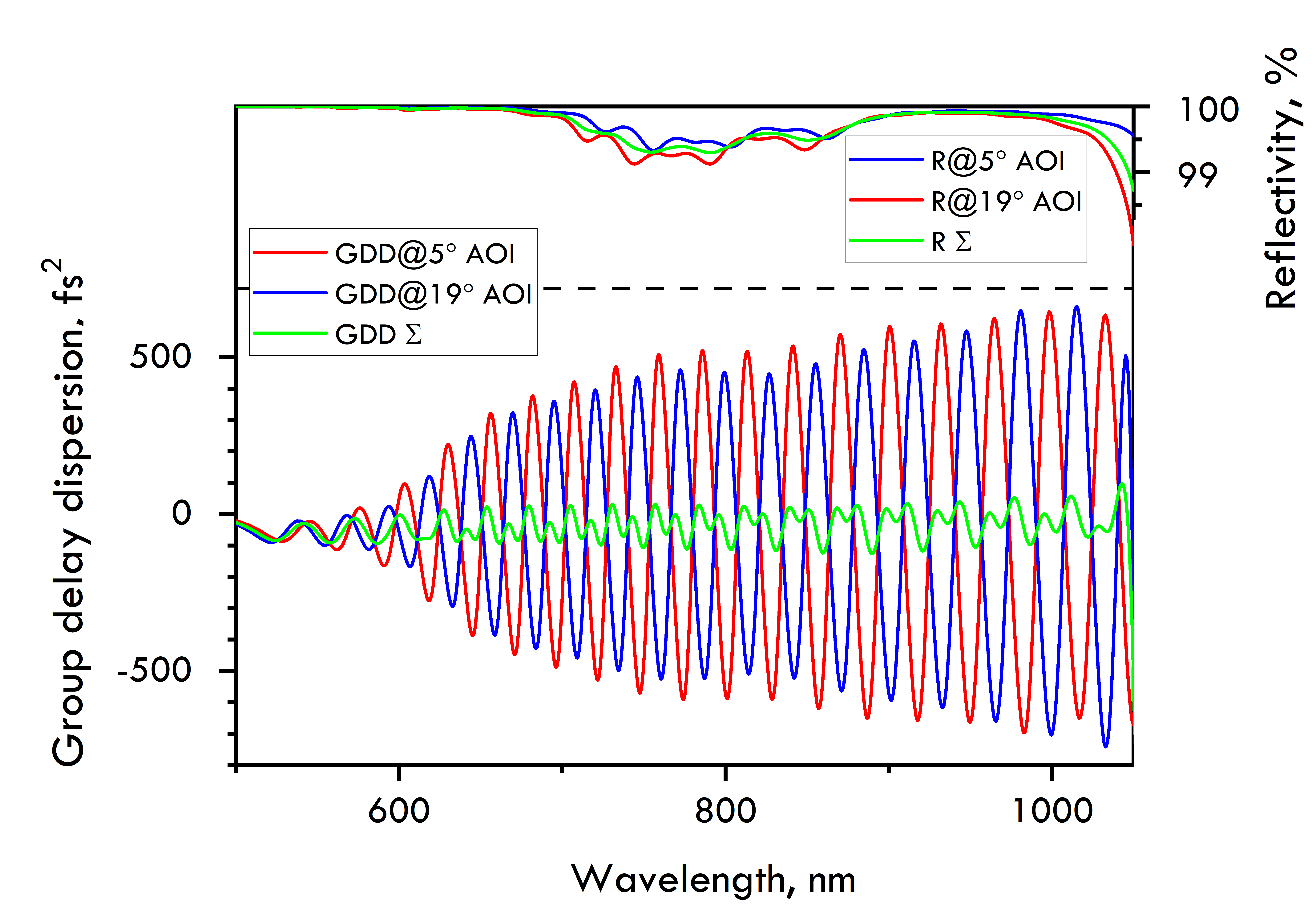
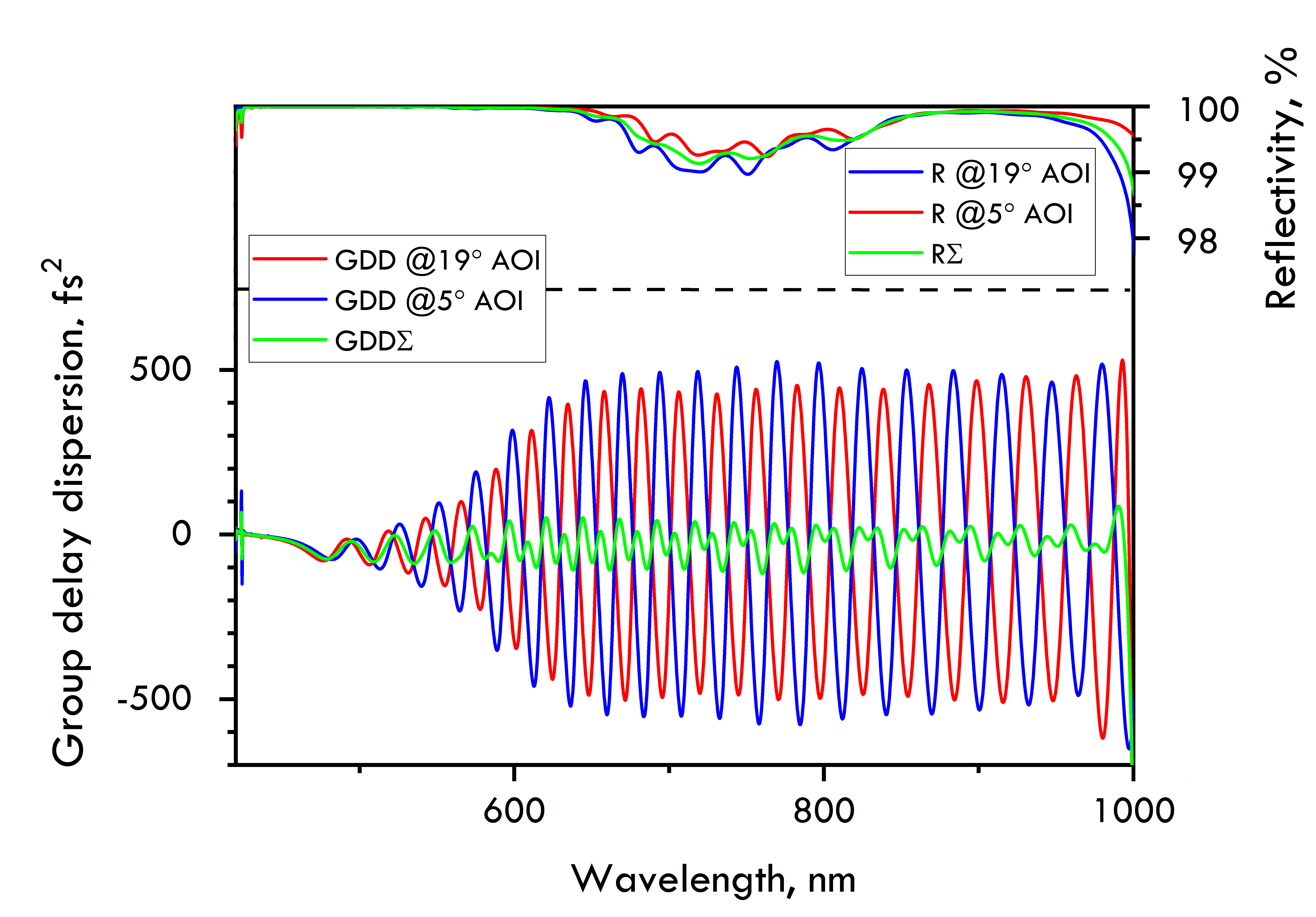
GDD −40 fs² · 500–1050 nm · AOI 5°/19°
Standard double-angle pair. Workhorse for Ti:Sapphire oscillators & sub-30 fs amplifiers.
GDD −40 fs² · 450–1000 nm · AOI 5°/19°
Newer DACM design. Smoother GDD oscillations than PC70; recommended for sub-15 fs applications.
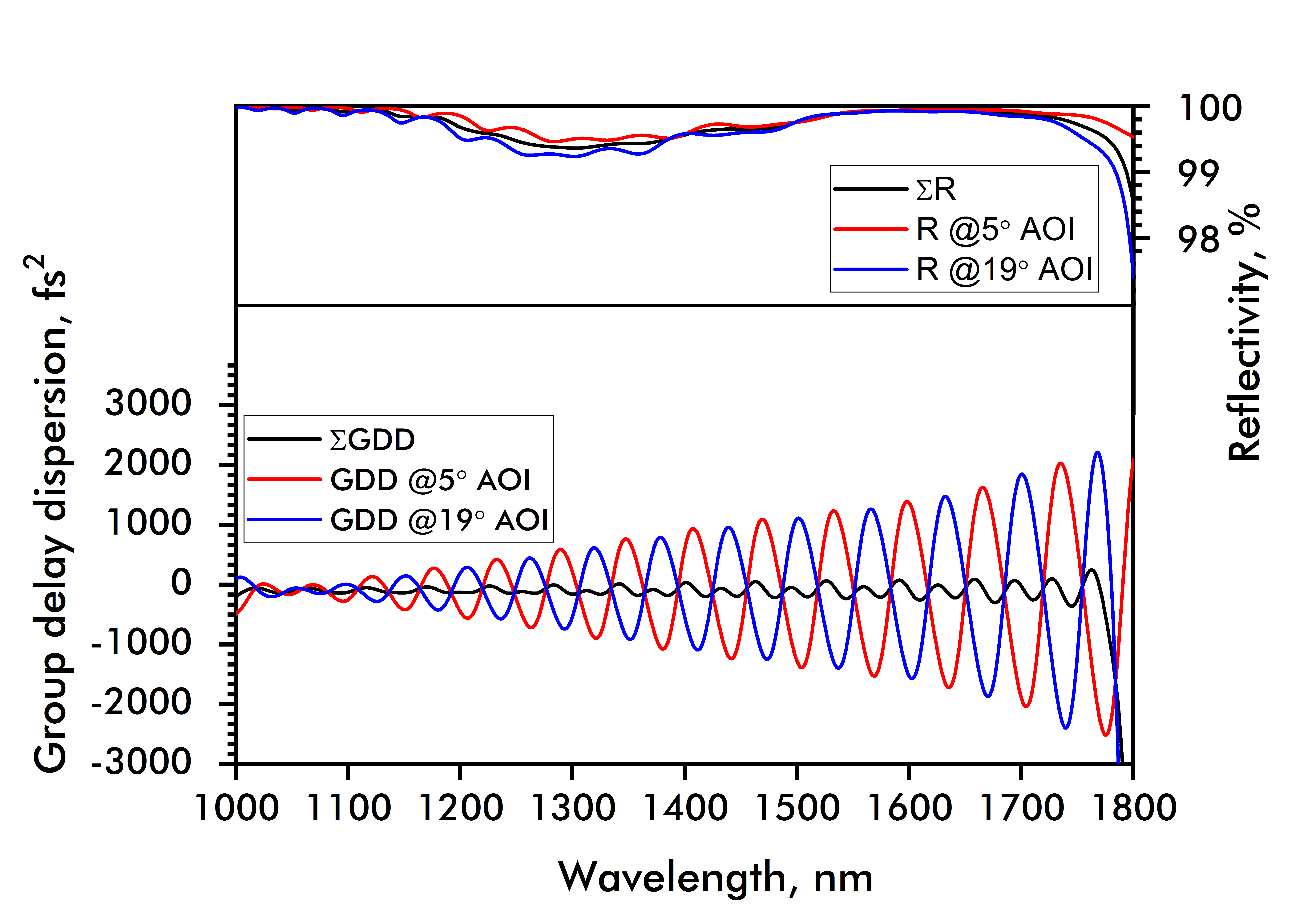
GDD −70 fs² · 1000–1800 nm · AOI 5°/19°
Octave-spanning NIR coverage. The go-to for mid-IR OPCPA front-ends and Cr:ZnSe.

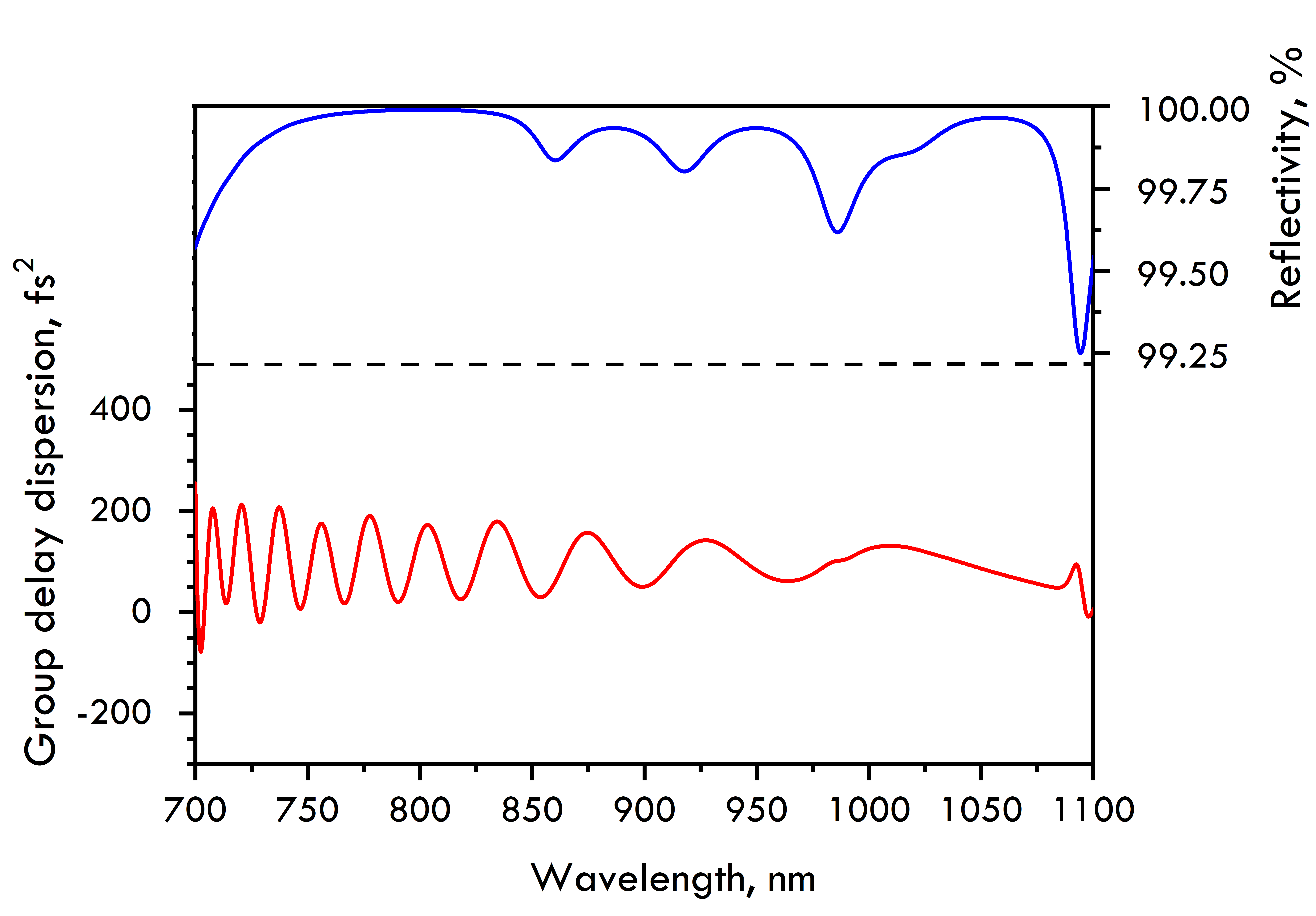
GDD −3 000 fs² · 1015–1050 nm · AOI 0°
75× more |GDD| than a standard CM in exchange for 3 % bandwidth. Ideal for compact Yb-fiber compressors.
GDD +100 fs² · broadband · AOI 0°
Positive-GDD variant for stretchers and chirped-pulse amplification front-ends. Pairs with PC70 for double-pass.
Filter by GDD, center wavelength, diameter, AOI, polarization, and brand.
Every formula in this guide has a click-and-drag implementation in our calculator suite. No registration, no login, runs entirely in your browser.
How much does N mm of glass stretch your pulse?
Convert between linear chirp rate and GDD.
Plan a 4–20 bounce compressor on a 12″ × 24″ table.
GDD & TOD of UVFS, sapphire, BBO, BK7, ZnSe, and more.
How short can your pulse be, given its spectrum?
Δλ → Δt for sech², Gaussian, square envelopes.
The CM alternative for very large GDD (> 10 000 fs²).
The classic tunable compressor — see why CMs replaced it.
Convert pulse energy + spot size → fluence in J/cm².